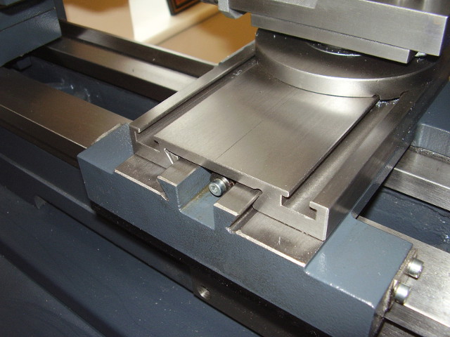
The cross-slide of the Wabeco D4000 Lathe is really too short. Mine is only 14.5mm longer than the dovetail slides on the saddle, so there is only 14.5mm travel before the far end of the fixed dovetails start to become exposed. When turning anything more than 29mm diameter or if the cross slide is retracted when drilling from the tailstock, the slideways are exposed to swarf.
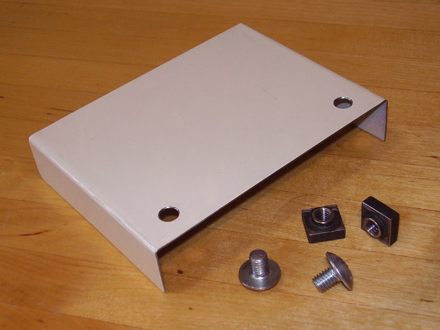
I made the simple guard shown below from sheet metal. It fixes to the cross slide T-slots, and is effective in keeping the slides clean over more than 70mm of cross slide travel.
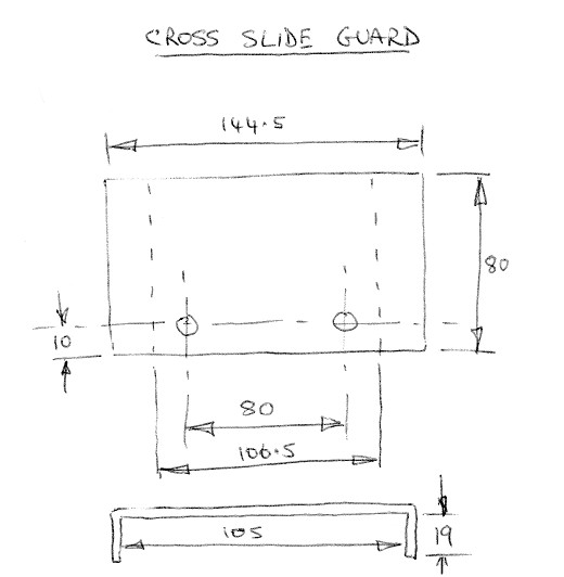
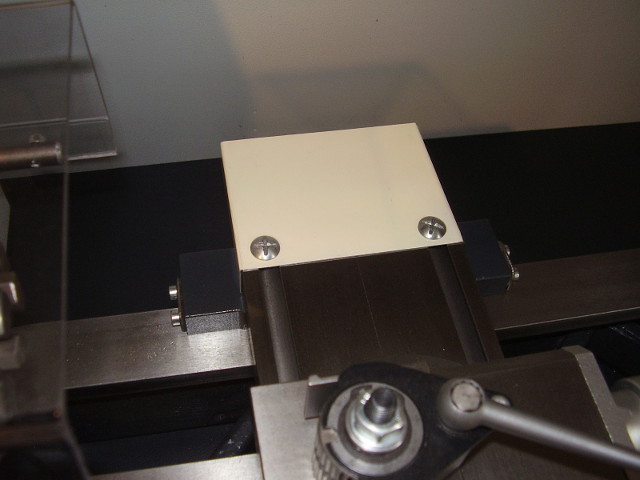
I used some painted 0.6mm steel salvaged from an old microwave oven, bent to shape. Slightly thicker material might be better. It is attached with some T-Nuts I had already, using M6 screws.
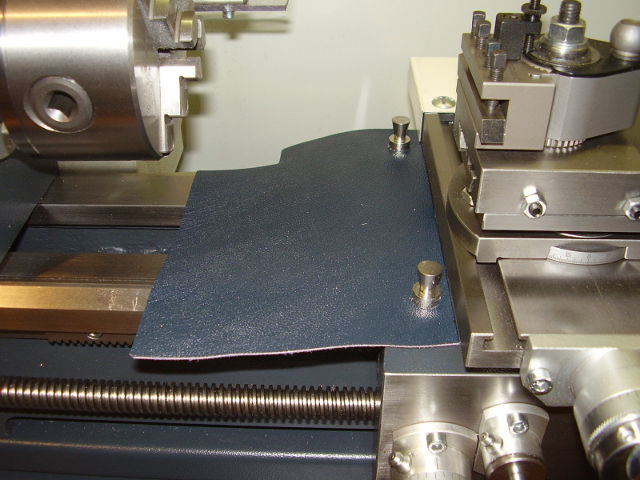
I made the protector shown here from some thin goatskin leather left over from another project. My initial prototype used thick polythene but this soon suffered from holes melted by hot chips.
While not keeping all swarf off the bedways it catches a lot of it. It is attached using two 'skittle' pot magnets, they are quite strong but have relatively little external magnetic field to attract ferrous swarf.
Don't believe everything in the Handbook!
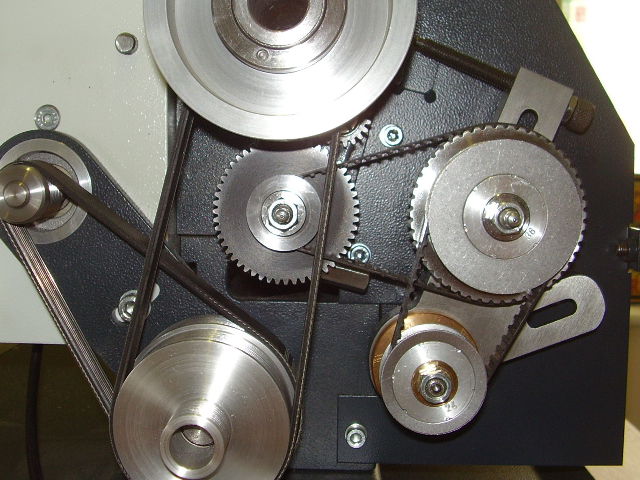
I needed to cut a thread of 1.5mm pitch but when I came to set up the change gears (pulleys) and toothed belts they wouldn't go together! Belt 'D' in the table in the Wabeco handbook was given as length 120 but was clearly too short to fit round 16T and 48T wheels...
The '140' belt was no good either, it was too long and the adjusting screw wouldn't reach...
In the end I managed to get a 1.5mm pitch using a different combination of wheel sizes.
I went through the table checking to see which combinations were actually useable. The errors are highlighted on the clip from the Wabeco handbook shown below.
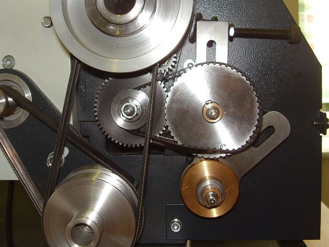
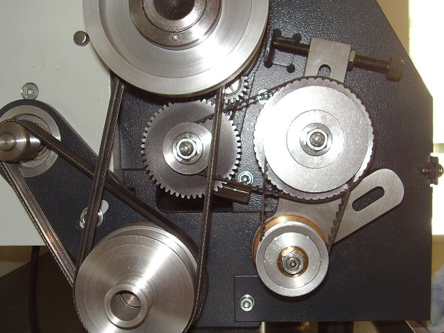
The combination of 16:48 wheels and 120 belt is used for a number of pitch settings in the table. What was needed was a belt with length somewhere between 120 and 140. These are standard XL size timing belts, are readily available and inexpensive so a length 130 belt was purchased. Note that the belt designation is twice the number of teeth, so a '130' belt has 65 teeth.
This shows the '130' belt in place wih the 16 and 48 wheels. It can be seen that the adjusting screw is now near mid position.
While checking the table I realised that in many cases there are other combinations of wheels and belts giving the same overall ratios. Some combinations fit better or have other advantages, e.g. a larger final wheel ('C') reduces the effects of inaccuracies such as eccentricity of the wheel or tooth pitch variations in the belt. The larger wheel also reduces the load on the belt due to the torque needed to turn the leadscrew.
I revisited this from time to time when I had a thread to cut, finding further errors in my 'revised' table and learning more about the constraints as time went on. Finally I decided to put together a spreadsheet that takes into account the geometry of the effective diameter of the toothed wheels, the belt lengths and the positions of the wheel arbors on the change gear quadrant, to calculate whether a chosen combination would fit.
The tables below have been validated using this spreadsheet. They are somewhat expanded on the Wabeco ones to cover the standard metric fastener pitches from M1.6 up, plus a comprehensive range of Imperial and BA threads. Only the standard set of wheels are used but the table assumes a 130 belt is available in addition to the supplied 2x 120 and 140.
The tables apply to the D4000 lathe. They may apply to its bigger brother the D6000, but I don't know whether the change gear geometry is the same.
Because the lathe has a metric leadscrew, the Imperial and BA threads have a small pitch error as shown in the tables. For some threads where the error is relatively larger e.g. 60TPI, this may or may not be significant depending on the application.
A printable pdf version can be downloaded here